|
|
Background
Notes: Over to Dave...
Modifying the Hi-Tec Ranger 3S FM radio set for up to 7 channels The Ranger 3S set uses a Philips PPM generation IC, the NE5044N. This is a general device capable of encoding up to 7 discrete channels into a digital Pulse Position Modulation bit-stream. Only three are used in this particular radio set. The IC takes analogue, DC voltage level, inputs and converts them into the delays which separate the pulses in the bit-stream. The input channels on the IC are pins 1 to 7 representing channels 1 to 7 respectively. Unused inputs are tied to ground (pin 8) which disables those channels completely such that they do not appear in the bit-stream at all.
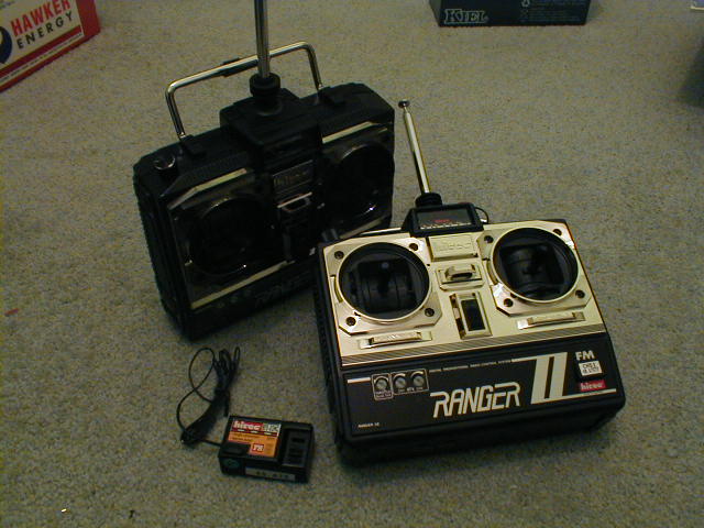
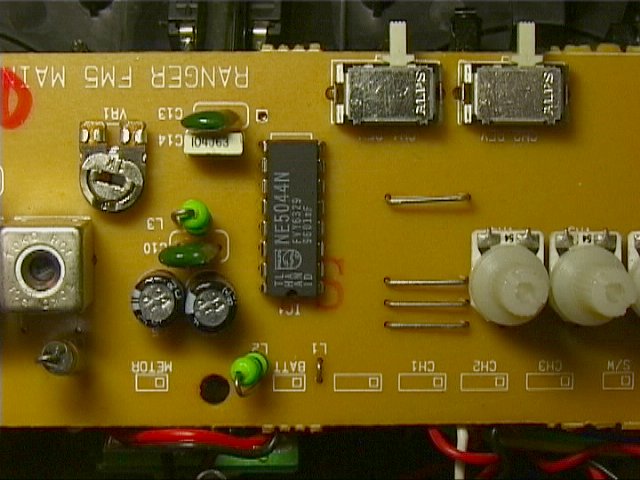
Figure 1 shows the topside of the board after the screws securing it have been removed. Note you have to remove the crystal before removing the board. If the notch in the IC is to your left then pin 1 is the bottom left corner and the pins are numbered anti-clockwise around the IC (see figure 1.5). 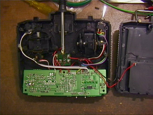 Figure 2 Figure 2 shows the board and transmitter. There are modifications to be made to both sides. It is worth noting that there is a fair bit of room beneath the board inside the transmitter if you wish to add components or small boards of your own. There is however very little room above the solder side of the board so the components we need to fit will be on the underside. The first thing is to decide how many channels you wish to transmit. For Tornado we use 6 even though we only transmit three signals. We have simply duplicated channels by connecting 1 to 5, 2 to 6 and 3 to 4. This means that we can sum these signals after decoding at the receiver and obtain some extra noise immunity over using just three channels. This is not the best utilisation of the extra channels but having realised that weight was not available in the robot we didn't fit the stuff the extra channels were going to be for . 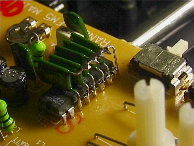 Figure 3
Having decided the number of channels, we will need to take precautions against the significant RF field generated by the transmitter itself. This means adding capacitors (10nF is a suitable value) to the input pins we wish to use. Figure 3 shows these capacitors added to the IC input pins 3 to 7. Pins 1 and 2 already have surface mounted caps fitted on the solder side of the board. Adding these five caps covers all 7 channels. If you don't need them all you can miss out the channels not used. Ceramic caps are recommended (even though I didn't use ceramic ones!) since they have a lower impedance at RF than most other types. It didn't seem to matter though. Some people might argue that these caps are not necessary but since I prefer to be cautious I would fit them anyway.  Figure 4 It is necessary to remove the ground connection from the input pins we wish to use. Carefully cut the tracks to the required pins with a craft knife. Be careful to note that, as in the case of the Ranger 3S, the ground track connects to the unused pins and then goes on to other parts of the circuit. It is necessary to make sure that these other parts remain connected to ground otherwise your transmitter won't work. Referring to figure 4 you can see two wires from a ground point at the bottom of the board connecting the parts of the circuit previously connected by the tracks which have been cut. The other two wires connect channel 1 to 5 and 2 to 6 and there is a short link between 3 and 4, but these will not be required for your mods as they are specific to Tornado. OK, as already stated the inputs take the form of DC voltages and they should only vary over a narrow range. The IC needs voltages that vary from 45 to 55% of the reference voltage available on pin 15 (5.04V) i.e. 2.27 to 2.77V to cover the full range of output span. The device you are adding (be it a potentiometer or whatever) should be fed by this reference voltage where possible. This will prevent drift of the output signal with temperature and battery voltage. For an example we shall connect a potentiometer to a spare channel to demonstrate how its done. The potentiometer should be of around 10K ohm value and a linear type to provide smooth, proportional control. The ends of the potentiometer are connected to ground (0V) and pin 15 (5.04V reference) respectively. The centre (wiper) connection is then fed to a resistor divider that takes the voltage span down to that necessary for full range. The following arrangement is used (Figure 5):  Figure 5 The two 33k resistors (R3 & R4) provide an effective half reference bias (5.04/2 V) with an effective resistance of 33/2 = 16.5k ohms. Resistor R2 sets the attenuation ratio such that the voltage swing at the IC is 2.27 to 2.77V as required. To calculate the value of this resistor we draw a Thevenin equivalent circuit. We consider the potentiometer at one extreme (in this case 5.04V). The Thevenin equivalent circuit is simplified to allow easy calculation of the unknown resistor (see Figure 6).
 Figure 6 - NOTE: These component numbers do not match those figure 5! The same approach can be used for a switch input like this (Figure 7):
 Figure 7 Modifying the Hi-Tec receiver for up to seven channels: This is a relatively simple mod since the chip used in the receiver has all seven outputs on it already, there is simply no connections made to the unused channels. Open up the receiver and locate the 4017 IC which is near the output sockets. This IC is a decoded counter with ten output pins. The first output is not used as this is active during the reset period when the transmitter waits for the next burst of PPM data. Output 2 is connected to servo output 1 and output 3 to servo 2 etc. The pins for each channel are listed, see also Figure 8:
The servo connectors carry 0V, supply (receiver battery +) and the appropriate output channel as listed above. You can thus connect as many servo outputs (up to seven) as you wish by adding connectors from a model shop etc. Good luck and happy roboteering! Any questions/comments can be directed to me at dgamble@supanet.com
Addendum
Where can I buy the Hi-Tec Ranger system?
|